Machine Vision Direct Header Logo
MachineVisionDirect.com
Support@MachineVisionDirect.com
1.800.834.5588
Smart Vision Lights Brand Banner

Smart Vision Lights LLM Downloads

LLM – LED Light Manager

Smart Vision Lights LLM Series Driver

LLM Description

The LLM can drive multiple lights of virtually any type or up to four individual zones or channels within an integrated photometric or multispectral ring light solution. Each program can contain up to six sequences with up to four lights set to continuous on, off, any intensity level in between, and even OverDrive strobe mode.

To program the four zones of a single LED illumination system such as a ring light or four separate LED light sources, simply connect the LLM to a computer via Ethernet cable and use the browser-based interface to program the light through a series of drop-down menus. The intuitive user interface makes it possible for technicians of any level to set image sequences and program intensities for each light.

The LLM system and light kit bundles initially will target 3D photometric stereo and 2D multi-light applications. When used in conjunction with specialized photometric stereo software from Matrox Imaging, Cognex, TeleDyne DALSA, SICK or MVTec, the lighting system can solve previously intractable tasks, such as finding a defect in the surface of a part. By capturing successive images of a stationary object as it is illuminated by a sequence of lights, photometric image processing software can determine the 3D surface orientation of every pixel across the object’s surface. The same technique can generate 2D images of multiple regions of interest using separate lights and/or cameras.

LLM is also appropriate for multispectral imaging solutions where the LED wavelengths – and not broad-spectrum white lights with optical filters in front of the sensor – are the spectral band selection mechanisms. Using the color of illuminating light as the spectral band selection mechanism can greatly reduce the cost of multispectral imaging solutions while increasing budgets for imaging applications.

LLM Downloads

Datasheet
User Manual
Dimension Drawing
Timing Chart
2D CAD File (DXF)
3D CAD File (STEP)

Order This Product

This product is available for purchase worldwide at Machine Vision Direct
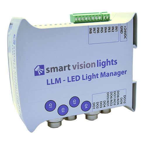
SVL LLM Light

Accessories

LLM Specifications

Electrical Input
Electrical Input Connector
Operating Current (No Load)
Number of Input Channels
Input Connector
Max Input Channel Voltage
On / Off Trigger Input
Input Channel Current
Output Channels
Output Connectors
Total Output Current (M12 Connectors)
Trigger Output Current (Per Channel)
Analog Output (Per Channel)
Slave Mode
Indicator Lights
Protection Circuitry
Programming Connector
SD Card
Reset Button
Mounting
Dimensions
Ambient Temperature
Ambient Humidity
Weight
Compliances
Warning
Terminal Blocks (Included with LLM)
24VDC +/- 5%
2 position screw terminal block – 14 AWG max wire size
70 mA
8 (including 1 input channel with interrupt capability)
8 position screw terminal block – 14 AWG max wire size
Not to exceed electrical input voltage
PNP mode: +4VDC or greater to activate (max 26VDC) NPN mode: GND ( less than 1VDC) to activate
PNP line: 4 mA @ 4VDC | 10 mA @ 12VDC | 20 mA @ 24VDC NPN line: 15 mA @ Ground (0VDC)
4 channels for lights plus 2 additional outputs, such as a camera trigger
4 5-pin M12 connectors 10 position screw terminal block – 14 AWG max wire size (configurable for NPN or PNP)
Total Average Output Current: 8 A - sum of all 4 channels (polyfuse protected) Maximum average output current per any 1 channel 2.8 A
PNP (sourcing): 65 mA NPN (sinking): 65 mA
Voltage: 1–10VDC, continuous mode intensity control Current: 0.5 mA max (with fault protection)
Selectable and configurable with DIP switches
Power on = green light Ethernet = 2 indicator lights
Polyfuse protection
Ethernet port
microSD card
Hold down for 3 seconds
DIN rail
H = 120 mm (4.7"), L = 107 mm (4.2"), W = 45 mm (1.8")
-18º–40º C (0º–104º F)
0–95% non-condensing
~233g
CE, RoHS
The user must ensure that the potential difference between any combination of applied signals does not exceed the supply voltage. The LED Light Manager (LLM) must not be used in an application where its failure could cause a danger to personal health or damage to other equipment.
2 position terminal block plug 8 position terminal block plug 10 position terminal block plug

Possible Part Configurations